A part can fit Garage Door Opener Wiring Diagram (4-Wire & 3-Button) physically and still be electrically or electronically incompatible. Confirm the number, polarity, generation, or receiver system before installation.
Correct wiring is critical for a garage door opener to work safely and reliably. In this guide, you will find clear garage door opener wiring diagrams for the most common systems – 4-wire wall controls and 3-button garage door opener switches.
This article covers:
- Garage opener wiring diagram basics
- 4 wire garage door opener wiring diagram
- 3 button garage door opener wiring diagram
- How to wire a garage door opener button
- Linear and Raynor garage door opener wiring
- Commercial 3-button wall station wiring
All diagrams and explanations are written for homeowners and technicians.
- The Numbers Worth Writing Down
- Garage Opener Wiring Diagram – Basics
- Common wire colors:
- 4 Wire Garage Door Opener Wiring Diagram
- Typical 4-wire configuration:
- 4 Wire Garage Door Opener Wiring Diagram (Text Layout)
- 3 Button Garage Door Opener Wiring Diagram
- 3 Button Garage Door Opener Wiring Diagram
- 3-Button Garage Door Opener Wiring Diagram (Text Layout)
- How to Wire a 3 Button Garage Door Opener
- Linear Garage Door Opener Wiring Diagram
- Raynor Garage Door Opener Wiring Diagram
- Commercial Garage Door Opener 3 Button Wall Station Wiring
- Summary
- Find the Control That Actually Saves the Setting
- The Working Sequence
- Narrow the Cause Before Buying Another Battery
- Stop Before This Becomes a Safety Fault
- Author
The Numbers Worth Writing Down
Garage Opener Wiring Diagram – Basics
Most garage door opener wall controls use low-voltage wiring (typically 12–24V).
These wires connect the wall control to the motor unit, not directly to household power.
Common wire colors:
- Red / White – power and signal
- Black / White – ground or secondary signal
⚠️ Always disconnect power before working on wiring.
4 Wire Garage Door Opener Wiring Diagram
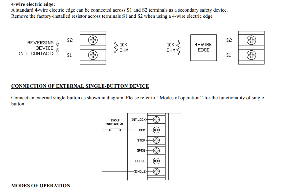
A 4-wire garage door opener is usually found in:
- Smart wall controls
- Keypad + wall button combinations
- Some Linear and commercial openers
Typical 4-wire configuration:
| Wire Color | Function |
|---|---|
| Red | Power (+) |
| White | Common / Ground |
| Black | Signal |
| Green | Auxiliary / Data |
4 Wire Garage Door Opener Wiring Diagram (Text Layout)
Motor Unit Terminals
-------------------
RED    -> Red wire
WHITE  -> White wire
BLACK  -> Black wire
GREEN  -> Green wire

Wall Control
------------
Red    -> Power
White  -> Common
Black  -> Signal
Green  -> Data / Smart control
This setup is common on Linear garage door opener wiring diagrams and newer smart systems.
3 Button Garage Door Opener Wiring Diagram
A 3-button garage door opener wall station usually controls:
- Up
- Down
- Stop
This design is extremely common in commercial garage door opener systems.
3 Button Garage Door Opener Wiring Diagram
| Button | Wire Connection |
|---|---|
| Up | Terminal 1 |
| Down | Terminal 2 |
| Stop | Terminal 3 |
| Common | Shared return |
3-Button Garage Door Opener Wiring Diagram (Text Layout)
[ UP ] ---- Wire 1 ---- Motor
[ DOWN ] -- Wire 2 ---- Motor
[ STOP ] -- Wire 3 ---- Motor
[ COM ] --- Common ---- Motor
This is also known as a 3 button garage door switch wiring diagram.
How to Wire a 3 Button Garage Door Opener
If you’re wiring a 3-button station:
- Run 3 separate control wires + common
- Match each button to its motor terminal
- Confirm STOP button interrupts both UP and DOWN circuits
This is critical for commercial garage door opener 3 button wall station wiring.
Linear Garage Door Opener Wiring Diagram
Linear garage door openers often use:
- 3-wire or 4-wire wall controls
- Color-coded terminals on the motor
Typical Linear garage door wiring diagram:
This also applies to Linear garage door opener wiring diagram requests.
Raynor Garage Door Opener Wiring Diagram
Raynor systems commonly mirror LiftMaster commercial layouts:
- 3-button wall stations
- Low-voltage control wiring
- Clearly labeled motor terminals
If your Raynor unit uses a 3 button garage door opener wiring, follow the commercial diagram above.
Commercial Garage Door Opener 3 Button Wall Station Wiring
Used in warehouses and shops:
- Mandatory STOP button
- Dedicated UP / DOWN circuits
- Heavy-duty wall stations
This wiring is required by code in many regions.
Summary
This guide covered:
- Garage opener wiring diagram
- 4 wire garage door opener wiring diagram
- 3 button garage door opener wiring diagram
- How to wire a garage door opener button
- Linear and Raynor wiring layouts
- Commercial wall station wiring
Find the Control That Actually Saves the Setting
For a standard wall button (single-button):
- Locate the wall control terminals on the motor
- Connect:
- Wire 1 -> Terminal 1
- Wire 2 -> Terminal 2
- Polarity usually does not matter for simple buttons
This applies to:
- How to wire a garage door opener button
- Wiring garage door opener button
- Door opener wiring diagram (basic systems)
The Working Sequence
For how to wire 2 3-button garage door opener stations:
- Each station must be wired in parallel
- Common wire shared
- Individual control wires kept separate
⚠️ Never wire stations in series.
Narrow the Cause Before Buying Another Battery
Stop Before This Becomes a Safety Fault
- Never connect wall control wires to AC power
- Use low-voltage cable only
- Secure wiring away from moving parts
Your next step with Garage Door Opener Wiring Diagram (4-Wire & 3-Button) is to verify the identifying number, then follow only the branch of this guide that matches it.
